 Canadian Special Risks" />
The Gas Metal Arc Welding (GMAW) process may be identified with several different modes of metal transfer which are based on the welding parameters such as, wire feed speed (current), voltage, electrode size, shielding gas composition, electrode chemistry, and type of power source.
The principal droplet transfer modes of interest in GMAW are: short-circuiting, globular, spray, and pulsed, in this first article we will focus on the first two modes of metal transfer: Short Circuit and Globular.
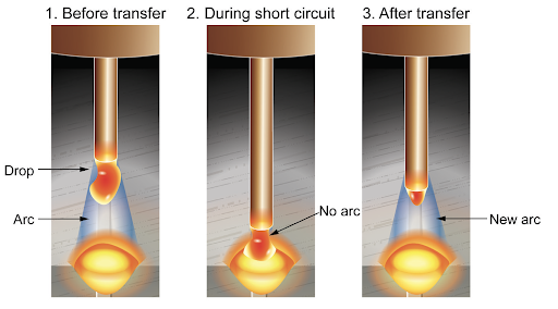
In the short-circuiting transfer mode, the amperage used in relation to the wire size, or current density, is relatively low. Consequently, the wire melts at the tip of the electrode, but the pinch force is not enough to detach it. The wire feeder continues to feed the wire and eventually the molten electrode tip will meet the weld pool.
When this happens, the constant voltage power source increases the amperage, which in turn increases electrode heating and the magnetic pinch effect acting at the electrode tip. The magnetic forces pinch off the droplet, which is then drawn into the weld pool by surface tension forces. Once the droplet is transferred there is a gap between the electrode and the weld pool for a millisecond and the arc is re-established. This process repeats itself very quickly, typically up to 200 times per second, so the short circuits and the arc will seem to be continuous. Figure 1 shows the process of short-circuiting transfer.

Figure 1, Short-Circuiting Transfer
In the short-circuiting transfer mode, the amount and speed at which the current increases during the short circuit must be controlled for the process to operate smoothly. This is the role of the power source and today most modern power sources automatically control the slope of the volt-amp curve to ensure transfer and minimize spatter.
The welding parameters such as current (wire feed speed) and voltage for short-circuit welding are relatively low and therefore best suited for welding of thin materials. This transfer mode can be used in all welding positions and for root passes on thicker steels.
A shorter contact-tip-to-work distance (6 to 8mm) is used when welding with this mode of metal transfer using an active shielding gas such as 100% CO2 or 75-80% Argon + 20-25% CO2. This transfer mode of metal transfer is generally not used on thicker materials because of the smaller diameter wires, 0.9 mm or smaller, and low currents below 200 amps. The resulting low heat input can cause fusion problems.
Therefore, welding codes and specifications for critical structural applications such as pressure vessels, bridges, naval vessels, etc., may prohibit the short-circuiting transfer mode if GMAW process is to be used for fabrication.
In recent years, equipment manufacturers have introduced new controlled short-circuit transfer technologies that are being use more and more in the fabrication of thin gauge steels and especially stainless steel.
Two modern day technologies are STT (Surface Tension Transfer) and RMD (Regulated Metal Deposition) which are know as “controlled dip transfer or modified short-arc processes”. These power sources combine inverter power source technology with advanced waveform control, providing improved welding solutions than traditional short-circuiting GMAW technology.
Applications for RMD and STT are the same as conventional short-circuiting GMAW; however, unlike conventional constant voltage (CV) GMAW power sources, the STT and RMD technologies have no knob for controlling the voltage. Each use current controls to adjust the heat, independent of the wire feed speed, so changes in electrode extension do not affect the heat input.
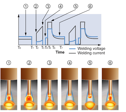
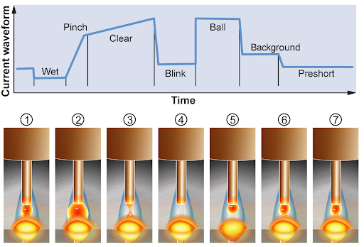
As a result, welds on thinner sheet metals can be produced without overheating or even melting through on thinner plate and distortion is minimized. Both the RMD and STT processes have been successfully applied to welding root passes in pipe or plate with improved bead appearance and reduced sidewall fusion defects compared to conventional short circuiting GMAW. Figure 2 shows the steps in the controlled dip transfer STT process and Figure 3 shows the steps in the controlled surface transfer RMD process.

Figure 2, STT Process.

Figure 3, RMD Process.
Globular transfer occurs as the current and voltage increase beyond those for short-circuiting transfer. The globular transfer mode is associated with the use of 100% CO2 shielding, but it has also seen heavy use with argon/CO2 blends. For general fabrication on carbon steel, it provides a mode of transfer which has lent itself to increased welding speed over short-circuiting transfer.
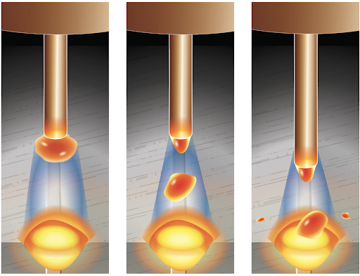
During the use of solid wire electrodes for GMAW, there is a transition where short-circuiting transfer ends and globular transfer begins. Globular transfer characteristically gives the appearance of large irregularly shaped molten droplets that are larger than the diameter of the electrode. The molten drop of metal at the electrode tip can reach a diameter 1.5 to 3 times the wire diameter. The irregularly shaped molten droplets fall from the electrode tip due to the force of gravity. The glob of molten metal splashes into the weld pool causing a violent expulsion of some liquid metal called spatter. Globular transfer in GMAW tends to produce higher spatter levels in significant amounts and is usually avoided for most applications.
Globular transfer does have very good penetration characteristics. However, as explained above, the main drawbacks of globular transfer are its high spatter formation together with irregular bead shapes and formation of numerous ceramic/slag islands. Figure 4 illustrates the Globular Transfer process showing the larger droplets.

Figure 4, Globular Transfer
In the next article we will cover the two other transfer types, Spray Transfer and Pulsed Transfer Modes.